7. The board
This chapter introduces the board, its hardware and how to boot it.
7.1. Hardware
The hardware documentation of Tibidabo can be found here:
http://downloads.architechboards.com/doc/Tibidabo/download.html
7.2. Power-On
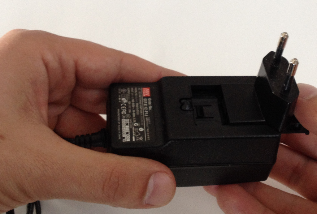
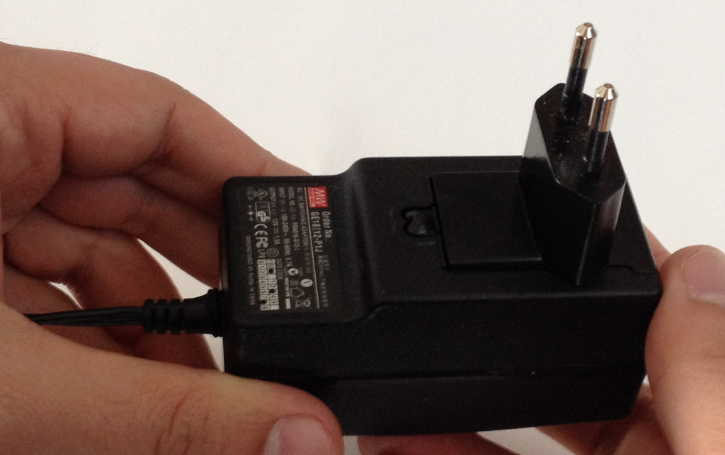
Tibidabo takes the power from connector CN19. The board is shipped with an external power adapter.
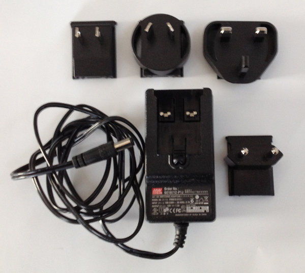
To assemble it, take the power socket adapter compatible with your country, plug it in the power adapter.
When in position, you should hear a slight click.
To power-on the board, just connect the external power adapter to Tibidabo connector CN19.
7.3. Serial Console
On Tibidabo there is the dedicated serial console connector CN1
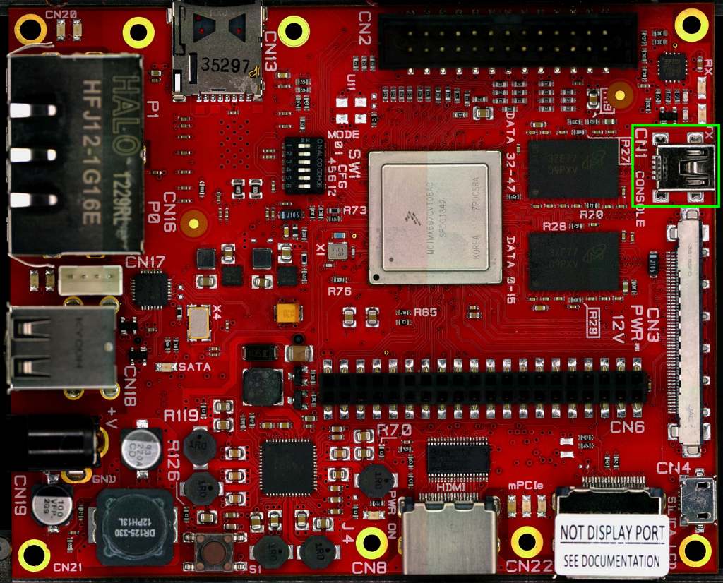
which you can connect, by means of a mini-USB cable, to your personal computer.
Note
Every operating system has its own killer application to give you a serial terminal interface. In this guide, we are assuming your host operating system is Ubuntu.
On a Linux (Ubuntu) host machine, the console is seen as a ttyUSBX device and you can access to it by means of an application like minicom.
Minicom needs to know the name of the serial device. The simplest way for you to discover the name of the device is by looking to the kernel messages, so:
- clean the kernel messages
sudo dmesg -c- connect the mini-USB cable to the board already powered-on
- display the kernel messages
dmesg- read the output
[ 2614.290675] usb 3-4: >new full-speed USB device number 4 using xhci_hcd
[ 2614.313854] usb 3-4: >New USB device found, idVendor=0403, idProduct=6015
[ 2614.313861] usb 3-4: >New USB device strings: Mfr=1, Product=2, SerialNumber=3
[ 2614.313865] usb 3-4: >Product: FT230X Basic UART
[ 2614.313868] usb 3-4: >Manufacturer: FTDI
[ 2614.313870] usb 3-4: >SerialNumber: DN002OZI
[ 2614.379284] usbcore: registered new interface driver usbserial
[ 2614.379298] usbcore: registered new interface driver usbserial_generic
[ 2614.379306] USB Serial support registered for generic
[ 2614.379310] usbserial: USB Serial Driver core
[ 2614.387899] usbcore: registered new interface driver ftdi_sio
[ 2614.387914] USB Serial support registered for FTDI USB Serial Device
[ 2614.387997] ftdi_sio 3-4:1.0: >FTDI USB Serial Device converter detected
[ 2614.388029] usb 3-4: >Detected FT-X
[ 2614.388031] usb 3-4: >Number of endpoints 2
[ 2614.388034] usb 3-4: >Endpoint 1 MaxPacketSize 64
[ 2614.388035] usb 3-4: >Endpoint 2 MaxPacketSize 64
[ 2614.388037] usb 3-4: >Setting MaxPacketSize 64
[ 2614.388260] usb 3-4: >FTDI USB Serial Device converter now attached to /dev/ttyUSB0
[ 2614.388288] ftdi_sio: v1.6.0:USB FTDI Serial Converters Driver
As you can see, here the device has been recognized as /dev/ttyUSB0.
Now that you know the device name, run minicom:
sudo minicom -wsIf minicom is not installed, you can install it with:
sudo apt-get install minicomthen you can setup your port with these parameters:
+-----------------------------------------------------------------------+
| A -    Serial Device      : /dev/ttyUSB0                              |
| B - Lockfile Location     : /var/lock                                 |
| C -   Callin Program      :                                           |
| D -  Callout Program      :                                           |
| E -    Bps/Par/Bits       : 115200 8N1                                |
| F - Hardware Flow Control : No                                        |
| G - Software Flow Control : No                                        |
|                                                                       |
|    Change which setting?                                              |
+-----------------------------------------------------------------------+
        | Screen and keyboard      |
        | Save setup as dfl        |
        | Save setup as..          |
        | Exit                     |
        | Exit from Minicom        |
        +--------------------------+
If on your system the device has not been recognized as /dev/ttyUSB0, just replace /dev/ttyUSB0 with the proper device.
Once you are done configuring the serial port, you are back to minicom main menu and you can select exit.
7.4. Let’s boot
The boot process of an i.MX6 processor is quite complex. After a Power On Reset (POR) the processor starts executing the internal ROM program. The boot mode is based on the binary value stored in the internal BOOT_MODE register:
| BOOT_MODE[1:0] | Boot Type |
|---|---|
| 00 | Boot from fuses |
| 01 | Serial downloader |
| 10 | Internal boot |
| 11 | Reserved |
BOOT_MODE[1] is read from SRC_BOOT_MODE1 pin (F12). BOOT_MODE[0] is read from SRC_BOOT_MODE0 pin (C12).
On Tibidabo, switches 1 and 2 of SW1 let you define the values for BOOT_MODE register:
- SW1 switch 1 controls BOOT_MODE[0]
- SW1 switch 2 controls BOOT_MODE[1]
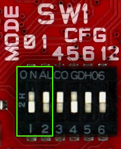
in the image BOOT_MODE[1:0] = 10 (Internal boot).
The other switches of SW1 are used for Internal boot mode and will be explained later in this chapter.
7.4.1. eFUSEs
eFUSEs are One Time Programmable (OTP) devices. The On-Chip OTP Controller (OCOTP_CTRL) manages reads/writes from/to eFUSEs and memory mapping of the values by means of shadow registers. You can blow the fuses by means of u-boot fuse command, be very careful because fuses are one time programmable only, a mistake will last forever! However, even if you manage to brik the board, you can always use it with the Serial downloader boot mode.
7.4.2. Boot from FUSEs
In boot from fuses mode the boot ROM uses the fuses values to decide how to boot. The boot flow is controlled by BT_FUSE_SEL eFUSE:
- if 1 the boot ROM will load the bootloader according to the state of eFUSEs,
- if 0 (the device has not yet been programmed) the boot ROM will jump to serial downloader mode.
Tibidabo is shipped with no fuse blown so you can blow the fuses when you think you are ready.
For example, to instruct the processor to boot from SD card you can blow the following fuses with u-boot fuse command:
fuse prog 0 5 0x00001040
fuse prog 0 6 0x00000010
where, the first command setup the boot from sd card, while the second command sets BT_FUSE_SEL = 1.
Again, if you want to instruct the processor to boot from SPI NOR you can blow the following fuses:
fuse prog 0 5 0x18000030
fuse prog 0 6 0x00000010
where the first command setup the boot from serial ROM, and the second command sets BT_FUSE_SEL = 1.
7.4.3. Serial Downloader
Serial downloader boot mode tells the processor’s boot ROM to load registers configuration and bootloader from USB. To work with this boot mode you need a micro USB cable to connect the board (connector CN4) to your Personal Computer and a software installed on your PC, speaking of which, if you have a Microsoft Windows operating system you need Freescale’s i.MX6 Manufacturing Tool that can be downloaded from:
http://www.freescale.com/webapp/sps/site/prod_summary.jsp?code=IMX6_SW
If you have a Linux operating system instead, you need Boundary Devices imx_usb_loader tool that can be obtained from their git repository:
git://github.com/boundarydevices/imx_usb_loader
To compile imx_usb_loader project you need libusb installed on your distribution. This is the set of commands needed on an Ubuntu machine to setup the tool:
sudo apt-get install libusb-1.0 libusb-dev libusb-1.0-0-dev
git clone git://github.com/boundarydevices/imx_usb_loader
cd imx_usb_loader
make
Once the tool is ready, power up the board, then you can download your u-boot.imx on the board with this command:
./imx_usb /path/to/your/u-boot.imx7.4.4. Internal Boot
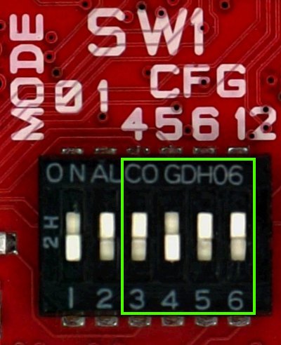
If BT_FUSE_SEL = 1 then all boot options are controlled by the eFUSEs, otherwise, if BT_FUSE_SEL = 0 then specific boot configuration parameters may be set using GPIO pins rather than eFUSEs. The use of GPIOs is intended for development only. If an error occurs, the boot ROM jumps to serial downloader boot mode. On Tibidabo, SW1 switches 3, 4, 5, 6 (along with a set of jumpers available on the bottom side of the board) can define a custom boot mode so you can simulate your configuration before blowing fuses.
| SW1[6:3] = BOOT_CFG[24]-BOOT_CFG1[6:4] | Boot Device |
|---|---|
| 1100 | SD regular boot |
| 1101 | SD fast boot |
| 0011 | Serial NOR |
| 0010 | SATA |
For example, this is the selection of the boot from SD card (fast boot)
7.4.5. Bootloader deploy
When you boot with serial downloader, you just do:
cd /path/to/imx_usb
./imx_usb /path/to/your/u-boot.imx
but when you boot from fuses or you want to use the internal boot you need to understand where the processor looks for the bootloader binary. If you want to boot from SPI NOR, you need to write the bootloader binary (u-boot.imx) to the flash memory. You can do it with from u-boot or from Linux as well. To do it from u-boot, you first need to read into memory a valid bootloader binary (from ethernet, SD card, mSATA or USB), then:
sf probe
sf erase 0x64000
sf write $loadaddr 0x400 $filesize
where loadaddr is an environment variable where the memory load address is defined, and filesize is the size of file u-boot.imx that has been previously loaded to memory. Be careful, by default the bootloader is configured to save the environment inside the SD card, not in the flash itself. If you prefer to save the environment inside the SPI NOR, open u-boot file:
/path/to/u-boot/sources/include/configs/tibidabo.hdefine macro CONFIG_ENV_IS_IN_SPI_FLASH by uncommenting it, comment CONFIG_ENV_IS_IN_MMC definition, and recompile the bootloader.
In case you want to boot from SD card, you need to write the bootloader starting at address 1024 on the medium, just inside the MBR gap. The first partition on the medium must start at an address that leaves enough room for then bootloader and its environment variables, block 8192 (with block size of 512) will be more then enough (the environment gets written/read on the SD card with an offset of 384KB and will be 8KB large). Good, but how do you write your u-boot binary on the SD card? If you do not care to customize the bootloader, and you built an image with Yocto/OpenEmbedded, you may have noticed that under the directory where Yocto/OpenEmbedded puts all the built images there is a file with extension .sdcard. Well, such a file is an iso and can be written as is to the SD card device, just:
sudo dd if=/path/to/image.sdcard of=/path/to/your/sd/card/deviceOnce the iso has been written, the SD card will have all you need to make it boot from it (it will have bootloader, kernel image, file system and kernel modules). Ok, but what if you want to rewrite just the bootload and not the all image? You can overwrite the bootloader on the SD card always with dd:
sudo dd if=/path/to/u-boot.imx of=/path/to/your/sd/card/device bs=1k seek=17.4.6. Bootscript
Once the bootloader has been properly deployed (see Bootloader deploy), you turn on the board, the bootloader gets loaded and starts running until it gets to the boot command. What happens next? Well, since the board have a lot of options from where to load the kernel and with which options run the kernel, where is the root file system, which video mode, etc..., you get the best result if you have a simple facility to customize the system boot process yourself instead of having a milion combinations script that doesn’t do exactly what you want it to do. The facility we are talking about is a simple u-boot script that the default boot command tries to load from, in order, mSATA, SD and tftp. When u-boot finds it, the script gets executed. That’s it. Here is an example of an u-boot script that tries to load the Linux kernel binary from the SD card first partition (the partition can be FAT, EXT2, EXT3 or EXT4), and tells the kernel to use the second partition of the SD card as root partition:
setenv bootargs ${bootargs} vmalloc=400M root=/dev/mmcblk0p2 rw,rootwait consoleblank=0 video=mxcfb0:dev=hdmi,1280x720M@60,if=RGB24 video=mxcfb1:dev=lcd,CLAA-WVGA,if=RGB666 fbmem=28M,10M
mmc dev 0
for file_system in fat ext2; do
    ${file_system}load mmc 0:1 ${loadaddr} /uImage && bootm ${loadaddr}
done
echo Impossible to boot from SD card partition 1
But that is an u-boot script, not the bootscript, to make it suitable as a bootscript you need to give it mkimage as input first. If you are not that comfortable with mkimage, you can have a simplified interface offered by create-bootscript.sh script. The usage is very simple, just run it like this:
./create-bootscript.sh -i /path/to/your/u-boot/script -o /path/to/where/to/emit/the/final/bootscriptwhere parameter -i stands for source file to take as input and -o stands for “binary” file to emit as output.
Copy the output file to where you want it to be found, that is:
- SD card, first or second partition in the root director
- mSATA, first or second partition in the root directory, or
- TFTP directory on your computer.
Important
Name the script exactly bootscript
7.5. Video modes
Tibidabo has three possible video outputs:
- HDMI via connector CN8
- LVDS via connector CN3, thought for SAMSUNG’s MODEL LTI460HN08 (connector pad numeration is reversed with respect to SAMSUNG monitor datasheet to direct use of a flat ribbon lvds cable)
- LVDS via display port connector CN22, meant for SILICA lvds display
Warning
Do not connect CN22 to DISPLAY PORT devices, CN22 uses just the connector of a DISPLAY PORT but the signals are meant to work just with Silica’s LCD (LVDS) displays.
If you want to boot using SILICA’s lcd as the only video output device you need to add to the kernel command line something like:
video=mxcfb0:dev=ldb,LDB-WVGA,if=RGB666 ldb=dul0
If you want to boot using SAMSUNG’s display as the only video output device you need to add to the kernel command line something like:
video=mxcfb0:dev=ldb,LDB-1080P60,if=RGB666 ldb=spl0
If you want to boot using a full HD HDMI display as the only video output device you need to add to the kernel command line something like:
video=mxcfb0:dev=hdmi,1920x1080M@60,if=RGB24
You can have a video output on more than one device and the resolutions stated before are not the only resolutions available. Keep also into account that the LVDS output has several working modes, like: spl, dul, sin, sep (please, have a look at /drivers/video/mxc/ldb.c).
7.6. Network
Tibidabo networking is powered by MARVELL Gigabit switch MV88E6123. On the board there is a dual ethernet connector, each connector has a name that is printed on the PCB (P0 and P1). The switch is supported both by u-boot and Linux kernel, however, u-boot support is limited so, if you need u-boot to load files from the network use just one of the two ports. Under Linux, instead, the default network configuration is:
root@tibidabo:~# ifconfig
eth0      Link encap:Ethernet  HWaddr 1E:ED:19:27:1A:B3
          UP BROADCAST RUNNING MULTICAST  MTU:1492  Metric:1
          RX packets:0 errors:0 dropped:0 overruns:0 frame:0
          TX packets:2 errors:0 dropped:0 overruns:0 carrier:0
          collisions:0 txqueuelen:1000
          RX bytes:0 (0.0 B)  TX bytes:644 (644.0 B)

lo        Link encap:Local Loopback
          inet addr:127.0.0.1  Mask:255.0.0.0
          UP LOOPBACK RUNNING  MTU:16436  Metric:1
          RX packets:0 errors:0 dropped:0 overruns:0 frame:0
          TX packets:0 errors:0 dropped:0 overruns:0 carrier:0
          collisions:0 txqueuelen:0
          RX bytes:0 (0.0 B)  TX bytes:0 (0.0 B)
but if you take a closer look, you discover that there are more interfaces available:
root@tibidabo:~# ifconfig -a
eth0      Link encap:Ethernet  HWaddr 1E:ED:19:27:1A:B3
          UP BROADCAST RUNNING MULTICAST  MTU:1492  Metric:1
          RX packets:0 errors:0 dropped:0 overruns:0 frame:0
          TX packets:2 errors:0 dropped:0 overruns:0 carrier:0
          collisions:0 txqueuelen:1000
          RX bytes:0 (0.0 B)  TX bytes:644 (644.0 B)

lo        Link encap:Local Loopback
          inet addr:127.0.0.1  Mask:255.0.0.0
          UP LOOPBACK RUNNING  MTU:16436  Metric:1
          RX packets:0 errors:0 dropped:0 overruns:0 frame:0
          TX packets:0 errors:0 dropped:0 overruns:0 carrier:0
          collisions:0 txqueuelen:0
          RX bytes:0 (0.0 B)  TX bytes:0 (0.0 B)

pt0       Link encap:Ethernet  HWaddr 1E:ED:19:27:1A:B3
          BROADCAST MULTICAST  MTU:1492  Metric:1
          RX packets:0 errors:0 dropped:0 overruns:0 frame:0
          TX packets:0 errors:0 dropped:0 overruns:0 carrier:0
          collisions:0 txqueuelen:0
          RX bytes:0 (0.0 B)  TX bytes:0 (0.0 B)

pt1       Link encap:Ethernet  HWaddr 1E:ED:19:27:1A:B3
          BROADCAST MULTICAST  MTU:1492  Metric:1
          RX packets:0 errors:0 dropped:0 overruns:0 frame:0
          TX packets:0 errors:0 dropped:0 overruns:0 carrier:0
          collisions:0 txqueuelen:0
          RX bytes:0 (0.0 B)  TX bytes:0 (0.0 B)
where pt0 is the network inteface corresponding to connector P0, while pt1 is the network interface corresponding to connector P1.
eth0 has a random MAC address assigned and, as you can see, pt0 and pt1 have the same address. To properly use the network you need to be sure that pt0 and pt1 have unique MAC addresses. You can change the MAC address of a specific network interface by means of this command:
ifconfig <port> hw ether <new mac address>substitute <port> with pt0 or pt1, and <new mac address> with the MAC address you decided to assign.
If you want that configuration to be brought up at boot you can add a few line in file /etc/network/interfaces, for example, if you want pt0 to have a fixed ip address (say 192.168.0.10) and MAC address of value 1e:ed:19:27:1a:b6 you could add the following lines:
auto pt0
iface pt0 inet static
    address 192.168.0.10
    netmask 255.255.255.0
    hwaddress ether 1e:ed:19:27:1a:b6
You can, of course, define the default configuration for pt1 as well.